Polycam
EagleEYE IV PTZ
Welcome to the wonderful world of salvaging hardware and giving it a new purpose.
Today we’re saving a Polycom EagleEYE IV from the bin. So if you have any lying around, this project is for you!
What’s it?
This effort in reverse engineering allows you to connect your old EagleEYE IV to your computer, use it as a webcam and control its orientation. You can even go further and turn it into a full-fledged ONVIF surveillance camera.
How?
Let’s not kid ourselves, this isn’t a three minutes project, but with the right tools, you too can salvage your camera.
You see, the camera is connected to its tv-box using an HDCI cable (see the documentation in the GitHub repo). As per the documentation, this provides an HDMI link, power and serial connection to transmit PTZ commands.
By cutting your cable, or soldering from a female LFH60 socket, you can access those three connections. HDMI can be directly plugged to an HDMI breakout board, serial can be connected to a USB dongle using the wonderful adapter from CircuitSurgery. Add an HDMI capture card and you can now obtain your video feed using any webcam-compatible software, and command your camera using Polycam!
Source code, precompiled binaries and more info are available on Github.
A reverse engineering black-hole
Why? How? Pourquoi? Well I got a story for you…
I got my hands on a full Polycom set, including control screen, mic, tv-box and camera. It seems like such a waste for everything to go to waste, so after a couple years of it sitting on my desk, I finally acted. Let’s break this open!
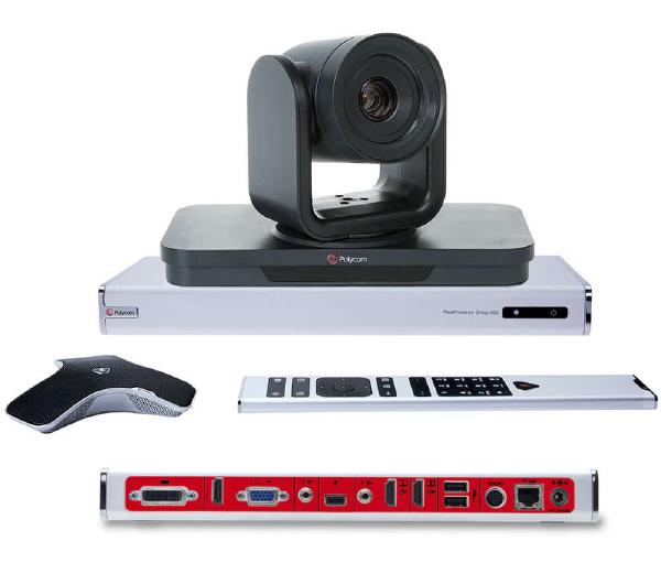 The beast
Step 1: what are we working with?
The tv-set being the brain of the operation, I started my journey by understanding how it was made. While the software itself doesn’t show anything meaningful, I got quite lucky after a full reset. The box restarted and began updating itself, listing packages such as software-xxx.apk being downloaded. Well my dear, this is an Android based platform!
And indeed, once opened you can access the SD card on which the whole system is installed. Which is exactly what I did, took the SD card out, plugged it into my laptop, and turned on a couple of flags to enable adb.
adb shell getprop | egrep "(ro.board|ro.product.cpu|arm.variant)"

[ro.board.platform]: [omap3]
[ro.product.cpu.abi2]: [armeabi]
[ro.product.cpu.abi]: [armeabi-v7a]
After this first success, I still needed to determine how the camera was connected to the TV set.
adb shell dmesg

# after connecting the camera to the TV set
<6>adv7604 1-0020: adv7604_worker: dev_id = 0
<6>rx_get_interrupts: pid = 2358, tgid = 2358
<6>adv7604 1-0020: rx_get_interrupts: Digital camera detected
<6>adv7604 1-0020: get_hdmi_resolution: Resolution value got is 1080p60
<6>adv7604 1-0020: rx_get_interrupts: Port1: Encrypted value from reg is 0
<6>adv7604 1-0020: rx_get_interrupts: Port1 has normal video
<6>adv7604 1-0020: rx_get_interrupts: Port1 state changed
<6>adv7604 2-0020: rx_get_interrupts: No sources present on Port2
<6>adv7604 2-0020: rx_get_interrupts: Port2 has Blue screen output
A quick search indicated that ADV7604 is a digital and analog capture chip, suggesting a strong chance that the camera is indeed outputting HDMI through its cable.
Thankfully the documentation was able to confirme this too.
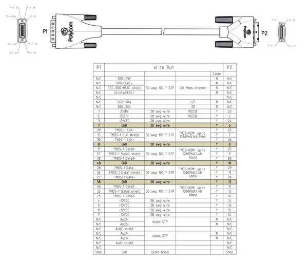 Official documentation for "HDCI Polycom EagleEye IV Digital Camera Cable"
Noticed something else? That’s right, two wires called RS232 Rx and Tx! That might come in handy later.
Step 2: tell me more, tell me more!
Before trying to send any kind of data over the RS232 wires, we need to know how to talk to the camera. Nothing in the documentation indicates anything related to the protocol used, so let’s try to capture what kind of data we should send. Let’s go over to our trusty adb and poke around.
adb shell busybox tail -F /data/log/messages

# Excerpt from logs after plugging in the camera
18:12:30.559 DEBUG    SMan: hd[0]: CameraBase: SM: WaitForNewCmdMsg: got message...
18:12:30.559 DEBUG    SMan: hd[0]: CameraBase: In: Command: 01
18:12:30.559 INFO     SMan: hd[0]: CameraJCCP: composeOrientationCmd: JCCP camera got orientation change to mode 1
18:12:30.559 INFO     SMan: hd[0]: CameraJCCP: Send 4 bytes: 83 41 3e 1
18:12:30.559 INFO     SMan: hd[0]: SrcMan: 83 41 3E 01
18:12:30.560 INFO     SMan: hd[0]: SrcMan: PortNear SrcManPortNear1 Controller 0 SendMessage: component_id: "cam1" serial_write { serial_bytes: "\203A>\001" }
18:12:30.560 INFO     SMan: hd[0]: SrcMan: SendMessage: local port controller
18:12:30.560 INFO     SMan: hd[0]: SrcMan: SendToEndpoint from SrcManPortNear1 to PortController
18:12:30.560 INFO     PCon: hd[0]: PcThreads: PC: NETRA0 input thread received CMD/REQ Msg - Comp_ID = cam1
18:12:30.560 INFO     PCon: hd[0]: PcThreads: PC_ProcessMsg: component_id: "cam1" serial_write { serial_bytes: "\203A>\001" }
18:12:30.560 INFO     PCon: hd[0]: PcSerial: Not CAM CTRL mode:  Send to CAMx ser HDCI
18:12:30.561 INFO     SMan: hd[0]: SrcMan: SendMessage: component_id: "cam1" error: kErrNoError
18:12:30.561 DEBUG    SMan: hd[0]: CameraBase: SM: WaitForNewCmdMsg: qHandler QLength is 0
18:12:30.561 DEBUG    SMan: hd[0]: CameraBase: SM: WaitForNewCmdMsg: blocking on dequeue...
18:12:30.567 INFO     PCon: hd[0]: PcSerial: PC: Serial read - sent notify from: PC:CAM1, num chars:1
18:12:30.567 INFO     PCon: hd[0]: PcSerial: CAM_Serial_ReadThread: component_id: "cam1" serial_bytes: "\240"
18:12:30.567 INFO     SMan: hd[0]: SrcMan: SMPlatformComponentNtfyHdlr, context 0x7b97c
18:12:30.567 INFO     SMan: hd[0]: SrcMan: PlatformComponentNtfyHdlr: component_id: "cam1" serial_bytes: "\240"
18:12:30.568 DEBUG    SMan: hd[0]: CameraBase: SM: WaitForNewCmdMsg: got message...
18:12:30.568 DEBUG    SMan: hd[0]: CameraBase: In: Response: a0
18:12:30.568 INFO     SMan: hd[0]: CameraJCCP: QRead 1 bytes
18:12:30.568 INFO     SMan: hd[0]: CameraJCCP: ProcessMessage: cam response: a0
18:12:30.568 INFO     SMan: hd[0]: CameraJCCP: rx: JCCP ACK
18:12:30.568 DEBUG    SMan: hd[0]: CameraBase: SM: WaitForNewCmdMsg: qHandler QLength is 0
18:12:30.568 DEBUG    SMan: hd[0]: CameraBase: SM: WaitForNewCmdMsg: blocking on dequeue...
18:12:30.568 INFO     PCon: hd[0]: PcSerial: PC: Serial read - sent notify from: PC:CAM1, num chars:1
18:12:30.568 INFO     PCon: hd[0]: PcSerial: CAM_Serial_ReadThread: component_id: "cam1" serial_bytes: "\222"
18:12:30.568 INFO     SMan: hd[0]: SrcMan: SMPlatformComponentNtfyHdlr, context 0x7b97c
18:12:30.569 INFO     SMan: hd[0]: SrcMan: PlatformComponentNtfyHdlr: component_id: "cam1" serial_bytes: "\222"
18:12:30.569 INFO     PCon: hd[0]: PcSerial: PC: Serial read - sent notify from: PC:CAM1, num chars:1
18:12:30.569 INFO     PCon: hd[0]: PcSerial: CAM_Serial_ReadThread: component_id: "cam1" serial_bytes: "@"
18:12:30.569 DEBUG    SMan: hd[0]: CameraBase: SM: WaitForNewCmdMsg: got message...
18:12:30.569 DEBUG    SMan: hd[0]: CameraBase: In: Response: 92
18:12:30.569 DEBUG    SMan: hd[0]: CameraBase: SM: WaitForNewCmdMsg: qHandler QLength is 1
18:12:30.569 DEBUG    SMan: hd[0]: CameraBase: SM: WaitForNewCmdMsg: blocking on dequeue...
18:12:30.569 INFO     SMan: hd[0]: SrcMan: SMPlatformComponentNtfyHdlr, context 0x7b97c
18:12:30.570 INFO     SMan: hd[0]: SrcMan: PlatformComponentNtfyHdlr: component_id: "cam1" serial_bytes: "@"
18:12:30.570 DEBUG    SMan: hd[0]: CameraBase: SM: WaitForNewCmdMsg: got message...
18:12:30.570 DEBUG    SMan: hd[0]: CameraBase: In: Response: 40
18:12:30.570 DEBUG    SMan: hd[0]: CameraBase: SM: WaitForNewCmdMsg: qHandler QLength is 2
18:12:30.570 DEBUG    SMan: hd[0]: CameraBase: SM: WaitForNewCmdMsg: blocking on dequeue...
18:12:30.570 INFO     PCon: hd[0]: PcSerial: PC: Serial read - sent notify from: PC:CAM1, num chars:1
18:12:30.570 INFO     PCon: hd[0]: PcSerial: CAM_Serial_ReadThread: component_id: "cam1" serial_bytes: "\000"
18:12:30.570 INFO     SMan: hd[0]: SrcMan: SMPlatformComponentNtfyHdlr, context 0x7b97c
18:12:30.571 INFO     SMan: hd[0]: SrcMan: PlatformComponentNtfyHdlr: component_id: "cam1" serial_bytes: "\000"
18:12:30.571 DEBUG    SMan: hd[0]: CameraBase: SM: WaitForNewCmdMsg: got message...
18:12:30.571 DEBUG    SMan: hd[0]: CameraBase: In: Response: 00
18:12:30.571 INFO     SMan: hd[0]: CameraJCCP: QRead 3 bytes
18:12:30.571 INFO     SMan: hd[0]: CameraJCCP: ProcessMessage: cam response: 92 40 00
18:12:30.571 INFO     SMan: hd[0]: CameraJCCP: rx: complete message 92 40 00
18:12:30.571 INFO     SMan: hd[0]: CameraJCCP: rx: Excuted
18:12:30.571 DEBUG    SMan: hd[0]: CameraBase: SM: WaitForNewCmdMsg: qHandler QLength is 0
18:12:30.571 DEBUG    SMan: hd[0]: CameraBase: SM: WaitForNewCmdMsg: blocking on dequeue...
18:12:30.575 INFO     PCon: hd[0]: PcConfig: Camera CHANGE callback: node sourceman.camera, NodeInst 1, sVar orientation, nVarInst 0
Yay! There are some very nice info there, mainly:
18:12:30.559 INFO     SMan: hd[0]: CameraJCCP: composeOrientationCmd: JCCP camera got orientation change to mode 1
18:12:30.559 INFO     SMan: hd[0]: CameraJCCP: Send 4 bytes: 83 41 3e 1
18:12:30.571 INFO     SMan: hd[0]: CameraJCCP: ProcessMessage: cam response: 92 40 00
18:12:30.571 INFO     SMan: hd[0]: CameraJCCP: rx: complete message 92 40 00
18:12:30.571 INFO     SMan: hd[0]: CameraJCCP: rx: Excuted
This indicates that to set the camera orientation to 1 (inverted? regular?) we need to send 83 41 3E 01 over the wire, and should expect 92 40 00 as a confirmation.
The documentation does indicate there is a telnet API, enabled through the web admin, allowing us to send commands like camera near setposition X Y Z. This new-found knowledge helped me build a script that tries all known commands and captures the associated relevant logs. You can find the result of those in the GitHub repo.
Some commands ended up being quite easy to understand, like playing with the camera orientation, setting the contrast etc, while some others like setting the position took a bit longer to synthesize.
As an exercise to the reader, try to understand how the position is encoded in the following captured data.
(0 -50000 0) -> 8d 41 51 04 00 03 68 00 00 00 03 00 04 7a
(0 -45000 0) -> 8d 41 51 04 00 03 68 00 00 19 03 00 04 7a
(0 -35000 0) -> 8d 41 51 04 00 03 68 00 00 4b 03 00 04 7a
(0 -30000 0) -> 8d 41 51 04 00 03 68 00 00 64 03 00 04 7a
(0 -25000 0) -> 8d 41 51 04 00 03 68 00 00 7d 03 00 04 7a
(0 -20000 0) -> 8d 41 51 24 00 03 68 00 00 16 03 00 04 7a
(0 -15000 0) -> 8d 41 51 24 00 03 68 00 00 2f 03 00 04 7a
(0 -10000 0) -> 8d 41 51 24 00 03 68 00 00 48 03 00 04 7a
(0  -5000 0) -> 8d 41 51 24 00 03 68 00 00 61 03 00 04 7a
(0  -3000 0) -> 8d 41 51 24 00 03 68 00 00 6b 03 00 04 7a
(0  -1000 0) -> 8d 41 51 24 00 03 68 00 00 75 03 00 04 7a
(0   -500 0) -> 8d 41 51 24 00 03 68 00 00 78 03 00 04 7a
(0   -200 0) -> 8d 41 51 24 00 03 68 00 00 79 03 00 04 7a
(0   -100 0) -> 8d 41 51 24 00 03 68 00 00 7a 03 00 04 7a
(0    -10 0) -> 8d 41 51 24 00 03 68 00 00 7a 03 00 04 7a
(0     -9 0) -> 8d 41 51 24 00 03 68 00 00 7a 03 00 04 7a
(0     -8 0) -> 8d 41 51 24 00 03 68 00 00 7a 03 00 04 7a
(0     -7 0) -> 8d 41 51 24 00 03 68 00 00 7a 03 00 04 7a
(0     -6 0) -> 8d 41 51 24 00 03 68 00 00 7a 03 00 04 7a
(0     -5 0) -> 8d 41 51 24 00 03 68 00 00 7a 03 00 04 7a
(0     -4 0) -> 8d 41 51 24 00 03 68 00 00 7a 03 00 04 7a
(0     -3 0) -> 8d 41 51 24 00 03 68 00 00 7a 03 00 04 7a
(0     -2 0) -> 8d 41 51 24 00 03 68 00 00 7a 03 00 04 7a
(0      0 0) -> 8d 41 51 24 00 03 68 00 00 7a 03 00 04 7a
(0      1 0) -> 8d 41 51 24 00 03 68 00 00 7a 03 00 04 7a
(0      2 0) -> 8d 41 51 24 00 03 68 00 00 7a 03 00 04 7a
(0      3 0) -> 8d 41 51 24 00 03 68 00 00 7a 03 00 04 7a
(0      4 0) -> 8d 41 51 24 00 03 68 00 00 7a 03 00 04 7a
(0      5 0) -> 8d 41 51 24 00 03 68 00 00 7a 03 00 04 7a
(0      6 0) -> 8d 41 51 24 00 03 68 00 00 7a 03 00 04 7a
(0      7 0) -> 8d 41 51 24 00 03 68 00 00 7a 03 00 04 7a
(0      8 0) -> 8d 41 51 24 00 03 68 00 00 7a 03 00 04 7a
(0      9 0) -> 8d 41 51 24 00 03 68 00 00 7a 03 00 04 7a
(0     10 0) -> 8d 41 51 24 00 03 68 00 00 7a 03 00 04 7a
(0    100 0) -> 8d 41 51 24 00 03 68 00 00 7a 03 00 04 7a
(0    200 0) -> 8d 41 51 24 00 03 68 00 00 7b 03 00 04 7a
(0    500 0) -> 8d 41 51 24 00 03 68 00 00 7c 03 00 04 7a
(0   1000 0) -> 8d 41 51 24 00 03 68 00 00 7f 03 00 04 7a
(0   3000 0) -> 8d 41 51 04 00 03 68 00 01 09 03 00 04 7a
(0   5000 0) -> 8d 41 51 04 00 03 68 00 01 13 03 00 04 7a
(0  10000 0) -> 8d 41 51 04 00 03 68 00 01 2c 03 00 04 7a
(0  15000 0) -> 8d 41 51 04 00 03 68 00 01 45 03 00 04 7a
(0  20000 0) -> 8d 41 51 04 00 03 68 00 01 5e 03 00 04 7a
(0  25000 0) -> 8d 41 51 04 00 03 68 00 01 77 03 00 04 7a
(0  35000 0) -> 8d 41 51 24 00 03 68 00 01 29 03 00 04 7a
(0  40000 0) -> 8d 41 51 24 00 03 68 00 01 42 03 00 04 7a
(0  45000 0) -> 8d 41 51 24 00 03 68 00 01 5b 03 00 04 7a
(0  50000 0) -> 8d 41 51 24 00 03 68 00 01 74 03 00 04 7a
Step 3: make it move!
Let’s not kid ourselves, the first steps took actually longer than what is looks like when summarized. But this next one? Oh god.
I now had both the physical way to send data, and the software understanding of which data to send, and which data to expect in return. Time to hook up some cables! After some trial and error I identified the RS232 wires inside the HDCI cable, and plugged them to a USB serial adapter. But when I sent data, nothing happened. The camera didn’t move, and no reply was received.
[Two years later.gif]
I strongly suspected that the voltages levels over the wire were not the right ones, and waited to have some money to spend on a digital oscilloscope to confirm.
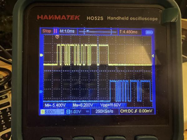 The Oscilloscope™: better at captures than a Poke-ball
Lo and behold! The data sent between the controller and camera uses logical levels distinct from RS232, at around -6V and +6V, resting level at -6V. Some wikipedia-ing indicated this corresponds to the lesser known standard RS423, like the one used by the old BBC Microcomputer. Which is exactly the type of cable I bought in the end, from the amazing CircuitSurgery!
After some soldering and giddy anticipation, I was able to make the camera move from my own Swift program!
IT'S ALIIIIIVE
Time to consolidate all the commands into a Swift CLI tool, and SwiftPTZ was born.
Step 4: there shall be light
Alright, time to get some video now. While the cables were identified earlier, nothing has been captured yet, and this looks like a good time to actually test it out.
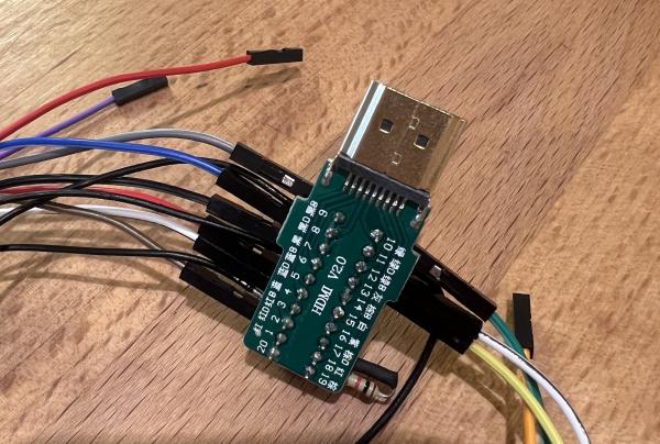 Looks legit
After creating a (horrifying) HDMI plug, let’s test it out. Per chance, I did find an old TV in the trash a couple of months before, which will definitely be used to test this out, I’d like to avoid breaking my actual display, thankyouverymmuch.
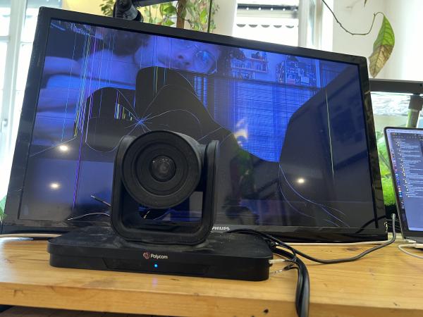 One last movie
Step 5: all done! (no)
Now equipped with proper communication, a functional HDMI input and a CLI tool to command the camera, all was well in a beautiful world and the project was finally done.
AHAHAHAHA.
No.
I mean. I had a good list of commands, don’t get me wrong, but what if there were commands unused by the original controller? What if they were super useful? Did you think of that? I did 🥴.
Enter step 5: fuzzing!
You see, all commands start with 8w xx yy [zz], w being the number of bytes in the total command, xx being kind of a group of similar commands, yy being the actual command, and optionally zz representing some argument. From my current list of commands, distinct groups appeared:
- 01: property getters, mostly for basic stuff like turn on/off
- 02: property getters, mostly for autofocus, exposure and the likes
- 03: property getters, mostly for color calibration
- 06: a single command replying with device info (firmware version, model)
- 41-43: property setters corresponding to 01-03 group of getters
- 45: actions, such as “move left”
Knowing the specific structure of the message encoding as well as a range of actual methods, I devise a plan to fuzz all potential commands of the camera, first by checking the reply of the camera, then by try to set newly-found registers to arbitrary values until the camera returned a success code. And I did discover a few! Understanding their actual purpose often took time, fidgeting with possible values while trying to see a difference on the video input (don’t get me started on the color calibration matrix), but it was quite the experience to explore that black box and reveal some secrets!
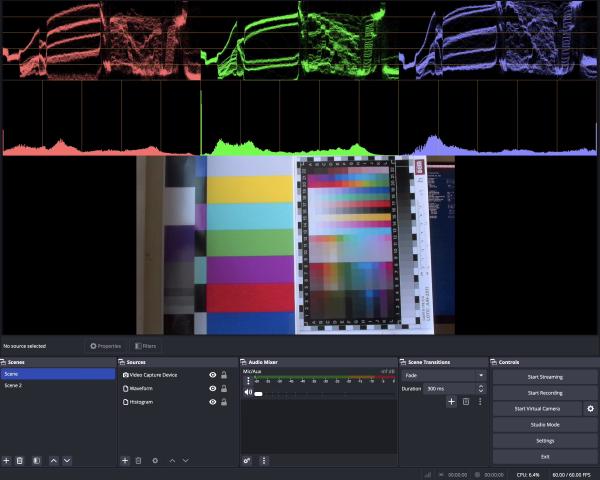 Feels like a fever dream by now
The full list of commands, their meaning and their discovery method is summed up in this document.
Step 6: bringing it all together
What you didn’t know, dear reader, is that this project happened because my dad found himself with a couple of full sets of Polycom, and wondered if it was possible to make them useful. We did have a goal of turning it into a surveillance camera, to check on my parents various animals outside.
According to Synology’s website, the standard for those seems to be ONVIF. Thankfully Roleo had already made a wonderful a configurable ONVIF server, so it was “only” a matter of updating SwiftPTZ to support some simpler commands to update PTZ incrementally and contributing zoom support to ONVIF simple server.
Please enjoy below the fruit of intense labor, and gaze on the camera being piloted by IP Camera Viewer, which I greatly recommend.
Finallyyyyyy
This brings our 3 years long journey to an end. I am quite happy about the results, particularly the commands newly discovered through fuzzing!